Scanalogic-2 EDU-KIT
Logic Analyzer and Signal Generator
SCANALOGIC-2 EDU-KIT
SCANALOGIC-2
EDU KIT (Educational kit) is a fun and educational kit allowing you to
build a high performance logic analyzer at home! Its a lower cost equivalent to the SCANALOGIC-2 Logic Analyzer whose performances have been proven over the last 3 years.
SCANALOGIC-2 EDU KIT is a 20 MHz, 256K Samples, 4 Channels logic analyzer that relies on a computer software (ScanaStudio) to visualise and analyze the captured signals.
Whether your a student on a budget or a hobbyist who enjoy creativity, this logic analyzer will suit you perfectly.
Basic Information
20 MSPS (Million samples per second).
Memory:256 K samples per channel (1M samples total).
Number of channels: 4 x Input/Output channels
Possible configurations:4 inputs, 4 outputs, 2 inputs and 2 outputs.
Decodes UART, SPI, I2C, 1-Wire and more
2V, 2.8V, 3.3V, 3.6V and 5V logic levels
Various trigger options
Top of page
Input features and characteristics
- Number of adjustable logic threshold groups: 2
- Adjustable logic levels for each group: 1.2V, 1.5V, 1.8V, 2.8V, 3.3V to 5V
- Number of integrated receivers for RS232 bus: 5
- Number of integrated receivers for LIN bus: 5
- Number of integrated differential lines receivers: 2 (can used for CAN, RS485, etc.)
- Activity LED integrated to ScanaPLUS device quickly indicates logic change on any line
- Input operating range 35V
- Absolute maximum input range 50V
- Input impedance 100K || 5pF
Top of page
Trigger options
- Pre-Trigger data display: 0% to 100% (allows to focus on post or pre-trigger data).
- Trigger modes: Rising edge, Falling edge, Logic change on a specific channel, logic change on any channel.
Capturing and analyzing signals
With the Scanalogic-2 logic analyzer, it has never been easier to capture streams of logic signals and analyze them using it's powerful features:
- Serial protocols sampling, decoding, debugging and analysis (like UART, SPI, CAN, LIN, I2C, 1-Wire, Manchester, maple bus…)
- Analysis of PWM signals, their frequencies and envelopes (Using the Fourier analysis feature).
- Monitor logic changes on digital signal lines.
- Store the captured data on files, to send them over the Internet to other users or for later playback!
- Captures images of the signals with all the timings, decoded data and markers.
- The Dual View features allows you can easily visually compare different data captures.
Top of page
Generating data
Generating your own data
- Generate all kind of PWM (pulse width modulation) signals to control motors drivers, RGB LEDs or other devices.
- Generate all kinds of FM (frequency modulation) signals. Can be used to test speakers or for ultrasound detection systems testing.
- Generate Serial data and pulses sequences to test your equipment/project using a very user friendly syntax
Playing back captured data
- Record serial data and play it back, as simply as you would record & playback a speech!
- Using the “mixed mode”, you can generate serial data on one channel (like UART), and record the response on another channels, all at the same time!
- This allows you to test your system in depth in a matter of minutes!
Top of page
Typical applications
- Analysis and debugging of digital electronics circuits
- Serial protocol decoding andanalysis(UART, I2C, SPI, CAN, 1-WIRE, LIN, Manchester,)
- Capturing signals over RS485 and CAN bus differential lines directly
- Digital PWM and FM signals analysis (using the FFT feature)
- Precise frequency and timing measurements (based on a 20 MHz time-base)
- Wave forms, serial signals and bit stream generation.
Scanalogic-2 Compared to other devices
Wondering how ScanaPLUS compares to other Logic Anlaysers already in the market?
- It’s one of the simplest devices to use of its class, easily mastered by beginners and professionals.
- The ScanaStudio PC software features all the smooth scrolling and navigation options you would expect from any professional software.
- It introduces a new useful feature, that we called the mixed mode, allowing you to generate/playback digital signals, while recording the response on other channels, all at the same time!
- It Provides computer-independent performances and timings. SCANALOGIC 2 provides a firm 20MSPS based on an on-device quartz oscillator.
- Sampling rate will never be compromised by the performance of your computer!
- We have put a lot of efforts to keep this product affordable for most students and hobbyists without compromise for the quality of the device, it's probes or the software.
- The best value for money in it's class
Top of page
Kit contents
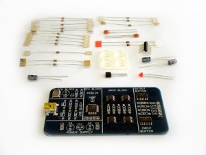
Scanalogic-2 EDU KIT comes as a PCB with pre-soldered components like the micro controller, the quartz oscillator and the SRAMs.
(basically all the difficult to solder, SMT components).
The rest of the components are to be soldered by the user (Resistors, capacitors, diodes, etc…).
The KIT also includes the gripper probes, with its user friendly color coding.
An instructions sheet is provided to help you place each component in the right place.
In order to solder your logic analyzer kit, you will need a soldering iron and and some solder wire and very basic soldering skills.
This product ships with the probes, a PCB with pre-soldered SMD components and all the remaining through-hole components.
A programmer is NOT needed as the micro controller chip is already programmed ready to use.
NOTE: The USB cable is not provided, a standard Mini-B type cable is required to connect the device to your computer.
